ImageProcessing.Compute.Plugin.ImageShader
Using WebGL and GLSL shaders the speed of online image processing in a web browser can be as fast as using an offline application. This is because the GLSL code is running directly on the graphics hardware and can benefit from the parallel computing power of hundreds (or thousands) of GPU shader cores.
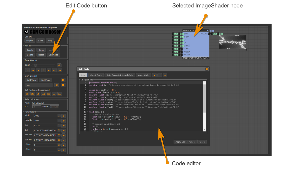
The ImageShader plugin node executes user-provided GLSL code and thereby allows creating a customized compute node for node-based image generation, processing, and compositing within the GSN Composer. Both, GLSL ES 1.0 and GLSL ES 3.0 are supported.
To this end, an online GLSL editor and validator is provided that is similar to other web-based GLSL tools, such as: ShaderToy, GLSL Sandbox, The Book of Shaders Editor, PixelShaders.com Editor, Kick.js Shader Editor Shdr, ShaderFrog, etc.
The main difference is that the GSN Composer is a node-based visual programming environment, which makes it very simple and convenient to provide the inputs (i.e., the uniform variables) for the custom image shaders. For every uniform variable that is created within the custom GLSL shader code, an input slot is added to the ImageShader node, which can be connected to other nodes of the dataflow graph. This makes shader development very fast and intuitive and frees the developer from writing many lines of support code to fill the uniform variables with values.
If the ImageShader node is selected in the graph area, the Edit Code button in the Nodes panel can be clicked. A dialog appears in which GLSL code can be entered.
The shader code is run for each pixel of the output image. The Red-Green-Blue-Alpha (RGBA) color value for
each pixel is set dependent on the computed value for the out variable, where 0.0 corresponds to full black and 1.0
is the full intensity.
To get started with GLSL programming, let's have a look at a very simple image shader that sets all pixels to red:
#version 300 es
precision highp float;
out vec4 outColor;
void main() {
  outColor = vec4(1.0, 0.0, 0.0, 1.0); // red=1.0, green=0.0, blue=0.0, alpha=1.0
}
The first line tells WebGL that the shader is using GLSL ES 3.0.
If this version directive is not specified in the first line of the shader code, GLSL ES 1.0 is used instead.
The second line defines the precision of floating point calculations,
where highp
means high precision. The next line defines the name of the out variable. The fourth line
is the start of the main function that is called for every output pixel. In the fifth line, the output color is set to red for every output pixel.
Using texture coordinates
An important variable that tells the image shader, for which pixel location it is executed is the 2-vector tc, which contains the current texture
coordinates of the processed pixel in the range [0.0, 1.0]. In the example below, the x- and y-texture-coordinates are used to set the intensity for the red and green channel, respectively.
#version 300 es
precision highp float;
out vec4 outColor;
in vec2 tc; // texture coordinate of the output image in range [0.0, 1.0]

void main() {
  outColor = vec4(tc.x, tc.y, 0.0, 1.0);
}
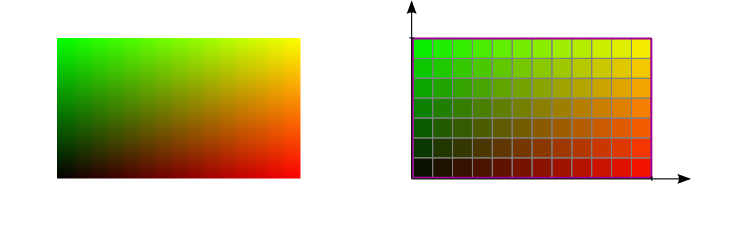
tc.xtc.yThe lower-left corner of the image represents the origin of the texture coordinate system with coordinates tc = (0.0, 0.0). The top right corner of the image is at tc = (1.0, 1.0).
Converting texture coordinates to pixel coordinates
Texture coordinates can be converted to (and from) pixel coordinates using the two functions shown below. To compute the size of one pixel in texture coordinates, 1.0 must be divided by the number of pixels in that dimension. The additional offset of 0.5 pixel is required because the center of the first pixel (with index 0) is located at half a pixel's size from the border of the image (with texture coordinate 0.0):
// pixel to textureCoord
float p2t(in float p, in int noOfPixels) {
  return (p + 0.5) / float(noOfPixels);
}

// textureCoord to pixel
float t2p(in float t, in int noOfPixels) {
  return t * float(noOfPixels) - 0.5;
}
To use these functions, we need to know the width and height of the output image. These values are passed to the image shader
via the width and height uniform variables and corresponding node input slots. In the example below, we draw
only a single pixel at index (3, 2) black.
#version 300 es
precision highp float;
out vec4 outColor;
in vec2 tc; // texture coordinate of the output image in range [0.0, 1.0]
uniform int width;
uniform int height;

// textureCoord to pixel
float t2p(in float t, in int noOfPixels) {
  return t * float(noOfPixels) - 0.5;
}

// round to nearest integer
int round2Integer(in float val) {
  return int(val + 0.5);
}

void main() {
  float px = t2p(tc.x, width);
  float py = t2p(tc.y, height);
  if(round2Integer(px) == 3 && round2Integer(py) == 2) { // if pixel index is (3,2)
    outColor = vec4(0.0, 0.0, 0.0, 1.0); // black
  }else{
    outColor = vec4(tc.x, tc.y, 0.0, 1.0);
  }
}
Uniform variables
For each uniform variable in the GLSL code, a corresponding slot with the same name is created at the input of the ImageShader node. The following table enlists the supported GLSL uniform types and the matching GSN data nodes that can be connected to the corresponding slot.
| GLSL uniform type | GSN data node |
| uniform int | PublicParameter.Data.Integer |
| uniform float | PublicParameter.Data.Float |
| uniform bool | PublicParameter.Data.Boolean |
| uniform vec2 | Matrix.Data.Matrix |
| uniform vec3 | Matrix.Data.Matrix |
| uniform vec4 | PublicParameter.Data.Color |
| uniform mat4 | Matrix.Data.Matrix |
| uniform sampler2D | ImageProcessing.Data.Image |
The only exception occurs if a variable of type "uniform sampler2D" is created and another variable of type "uniform int" that starts with same variable name plus "Width" or "Height". In this case, the integer variable is not exposed as an input slot. Instead, the width and height properties are gathered from the image.
A description and a default value can be set within a comment in the same line after the definition of a uniform variable:
uniform float blue; // description="The value of the blue channel" defaultval="1.0"
uniform vec4 col; // description="An input color" defaultval="1.0, 0.0, 1.0, 1.0"
uniform sampler2D img; // description="An input image"
uniform int imgWidth; // not exposed as slot but gathered from "img"
uniform int imgHeight; // not exposed as slot but gathered from "img"
Texture parameters
For a uniform variable of type "uniform sampler2D" texture parameters can be selected using name-value pairs in the comment after its definition. This includes magnification and minification filters and wrap parameters. The following table enlists the supported options:| Texture Parameter Name | Possible Values |
| mag_filter | NEAREST (default) LINEAR |
| min_filter | NEAREST LINEAR LINEAR_MIPMAP_NEAREST (default) LINEAR_MIPMAP_LINEAR |
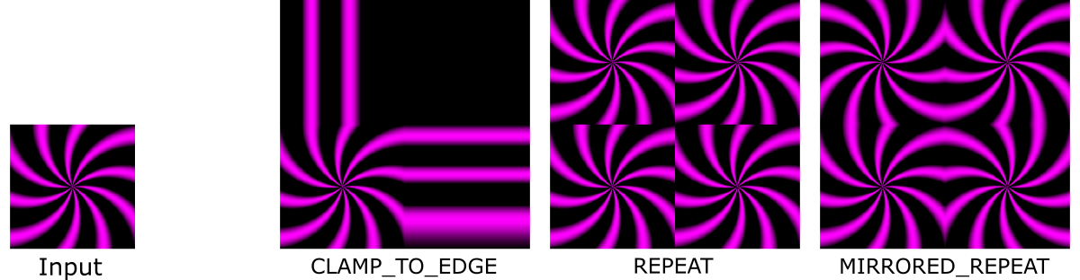
| wrap_s | CLAMP_TO_EDGE (default) REPEAT MIRRORED_REPEAT |
| wrap_t | CLAMP_TO_EDGE (default) REPEAT MIRRORED_REPEAT |
As an example, the following code multiplies the texture coordinates by 2.0 such that they are afterwards in range [0.0, 2.0] and the wrap parameter of the input texture "inputImage" becomes relevant:
#version 300 es
precision highp float;
out vec4 outColor;
in vec2 tc; // texture coordinate of the output image in range [0.0, 1.0]
uniform sampler2D inputImage; // wrap_s="REPEAT" wrap_t="REPEAT"

void main() {
  outColor = texture(inputImage, 2.0 * tc);
}
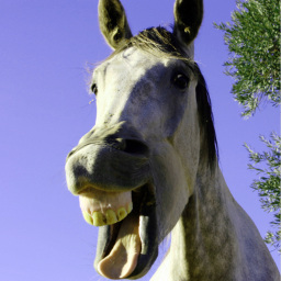
Accessing the mouse position
In this example, the mouse position is used to create a deformation field that is applied to the input image
#version 300 es
precision highp float;
out vec4 outColor;
in vec2 tc; // texture coordinate of the output image in range [0.0, 1.0]
const float PI = 3.14159265359;
uniform sampler2D inputImage;
uniform float mouseX;  // description="The mouse x-position in range [0.0, 1.0]"
uniform float mouseY;  // description="The mouse y-position in range [0.0, 1.0]"
uniform float effectSize; // description="Size of effect" defaultval="0.125"

void main() {
  vec2 offset = tc - vec2(mouseX, 1.0-mouseY);
  float dist = length(offset);  // distance of current pixel to mouse
  float scaledDist = 8.0/effectSize * dist; // scaled distance
  float weight =  (scaledDist > PI)? 0.0 : sin(scaledDist); // compute weighting
  outColor = texture(inputImage, tc - 0.25 * offset * weight);
}
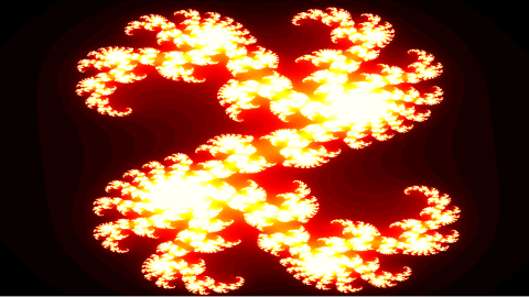
Example: Julia Set Fractal
Few lines of shader code can sometimes generate a very interesting output. In this example, the Julia set fractal is computed:
#version 300 es
precision highp float;
out vec4 outColor;
in vec2 tc; // texture coordinate of the output image in range [0.0, 1.0]

const int maxIter = 50;
const float iterStop = 5.0;
uniform float cx; // description="Seed X" defaultval="0.345"
uniform float cy; // description="Seed Y" defaultval="0.065"
uniform float scaleX; // description="Scale in X direction" defaultval="3.0"
uniform float scaleY; // description="Scale in Y direction" defaultval="3.0"
uniform float offsetX; // description="Offset in X direction" defaultval="0.0"
uniform float offsetY; // description="Offset in Y direction" defaultval="0.0"

void main() {
  // scale or shift output
  float zx = scaleX * (tc.x - 0.5 + offsetX);
  float zy = scaleY * (tc.y - 0.5 + offsetY);

  // compute mandelbrot set
  int ii;
  for(int i=0; i < maxIter; i++) {
    ii = i;
    float x = zx * zx - zy * zy + cx;
    float y = zy * zx + zx * zy + cy;
    if((x * x + y * y) > iterStop) break;
    zx = x;
    zy = y;
  }
  // number of iterations determines grayscale value
  float gray = 0.0;
  if(ii < maxIter) gray = float(ii) / float(maxIter);
  outColor = vec4(gray, gray, gray, 1.0);
}
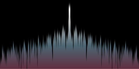
Example: Analyse Sound
An image shader can also react to the currently playing sound. To this end, the current spectrum and wavefront data can be passed to the shader as images:
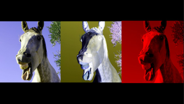
Multiple Output Images
GLSL ES 3.0 supports rending to multiple draw buffers by specifying multiple out variables.
To this end, the GLSL layout qualifier must be used with consecutive locations starting from 0.
In the following example, three simple image effects are written to three different output images.
#version 300 es
precision highp float;
layout(location = 0) out vec4 color; // description="Copy of original image"
layout(location = 1) out vec4 inverse; // description="Image with inverted colors"
layout(location = 2) out vec4 red; // description="Only the red channel"
in vec2 tc; // texture coordinate of the output image in range [0.0, 1.0]
uniform sampler2D inputImage;

void main() {
  color = texture(inputImage, tc);
  inverse = vec4(1.0 - color.rgb, 1.0);
  red = vec4(color.r, 0.0, 0.0, 1.0);
}
3D
Image shaders can also produce 3D effects, but all 3D information must be generated procedurally inside the shader or must be extracted from input textures. Often it is easier to split the task into a vertex and a fragment shader. To this end, the GLSL Shader Plugin is provided that allows using the complete WebGL shader processing pipeline.
Furthermore, there is a special pre-compiler for the ImageShader plugin node that simulate the ray tracing shader pipeline from the Vulkan GL EXT ray tracing specification. More information about this pre-compiler is given here.
Please use the contact form or visit the forum on Reddit if you have questions or suggestions for improvement.