3D.Compute.Plugin.Shader
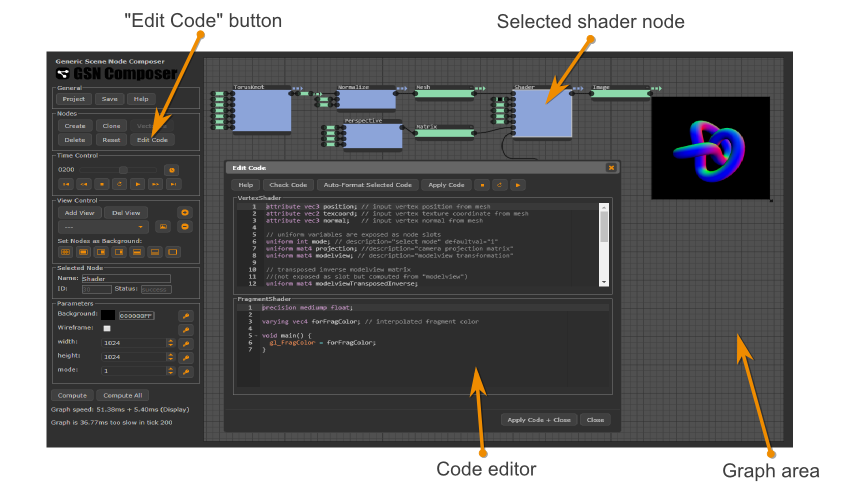
The Shader plugin node executes user-provided GLSL vertex and fragment shaders and thereby allows creating a customized compute node for 3D rendering within the GSN Composer.
To this end, a web-based GLSL editor and validator is provided that is similar to other online GLSL tools, such as: ShaderFrog, Shdr, WebGLStudio, Kick.js Shader Editor Firefox WebGL Shader Editor, etc.
The main difference is that the GSN Composer is an online node-based visual programming environment, which makes it very simple and convenient to provide uniform variables and 3D meshes for the shaders. For every uniform variable that is created within the custom GLSL shader code, an input slot is added to the shader node, which can be connected to other nodes of the dataflow graph. This makes shader development very fast and intuitive and frees the developer from writing many lines of support code to fill the uniform variables with values. 3D meshes of standard primitives can be generated with the corresponding nodes (e.g. cubes, spheres, cylinders, cones, etc.). Furthermore, custom 3D meshes can be uploaded in Wavefront OBJ format.
Importantly, the used GLSL code is generic and can be applied directly in other OpenGL/GLSL applications. Thus, the shader editor within the GSN Composer is a convenient tool for rapid prototyping of GLSL shaders. It is especially intended as a resource for computer graphics courses and tutorials.
The Shader plugin node, described here, aims at 3D rendering with vertex and fragment shader code. If you are new to shaders, a simpler starting point might be generating image shaders with the ImageShader plugin node of the GSN Composer. It is a bit less complicated because typically fewer inputs are required and only fragment shader code needs to be written. Well-known web-based tools such as ShaderToy or GLSL Sandbox are also image shaders and the examples on these websites can be a great source of inspiration.
If the Shader node is selected in the graph area, the Edit Code button in the Nodes panel can be clicked. A dialog appears in which GLSL vertex and fragment shader code can be entered. Both, GLSL ES 1.0 and GLSL ES 3.0 are supported.
To get started with shader programming, the first examples that are given here follow closely Chapter 9 of the lecture on graphics programming given at the University of Marburg. Other chapters of the lecture might be helpful if you are new to OpenGL programming in general.
First Shader
#version 300 es
precision highp float;
in vec3 position; // input vertex position from mesh
in vec2 texcoord; // input vertex texture coordinate from mesh
in vec3 normal;   // input vertex normal from mesh

out vec2 tc; // output texture coordinate of vertex
out vec3 fn; // output fragment normal of vertex

void main() {
  tc = texcoord;
  fn = normal;
  gl_Position = vec4(0.5 * position, 1.0);
}
#version 300 es
precision highp float;
out vec4 outColor;
in vec2 tc; // texture coordinate of pixel (interpolated)
in vec3 fn; // fragment normal of pixel (interpolated)

void main() {
  outColor = vec4(tc.x, tc.y, 0.0, 1.0);
}
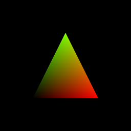
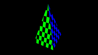
The mesh that is passed into this shader contains a triangle with three vertices. The vertex position are (-1.0, -1.0, 0.0), (1.0, -1.0, 0.0), and (0.0, 1.0, 0.0). Corresponding texture coordinates are (0.0, 0.0), (1.0, 0.0), (0.5, 1.0). The three vertex normals are all pointing in positive z-direction (0.0, 0.0, 1.0).
The vertex shader is called for each vertex of the input mesh and the current vertex position, texture coordinate, and normal are passed to the shader by the corresponding in variables
at the top of the vertex shader code. Input texture coordinates and normal are handed over without
modifications to the corresponding output out variables of the vertex shader.
The build-in variable gl_Position is assigned the output position of the vertex. In this example, the input position is scaled by 0.5.
The fragment shader is called for each pixel of the output image. Therefore, it is also often referred to as "pixel shader". The texture coordinates and normal from the vertex shader are interpolated
by the rasterizer in OpenGL's internal pipeline and the interpolated values for the current pixel are passed into the fragment shader by the in variables.
The used-defined out variable outColor is set to the output color of the pixel. In this example, the
x- and y-coordinate of the texture vector are assigned to the red and green color channel, respectively.
Uniform variables
Uniform variables are used to pass data that remains constant for all vertices/fragments during a rending pass. For each uniform variable in the GLSL code, a corresponding slot with the same name is created at the input of the shader node. The following table enlists the supported GLSL uniform types and the matching GSN data nodes that can be connected to the corresponding slot.
| GLSL uniform type | GSN data node |
| uniform int | PublicParameter.Data.Integer |
| uniform float | PublicParameter.Data.Float |
| uniform bool | PublicParameter.Data.Boolean |
| uniform vec2 | Matrix.Data.Matrix |
| uniform vec3 | Matrix.Data.Matrix |
| uniform vec4 | PublicParameter.Data.Color |
| uniform mat4 | Matrix.Data.Matrix |
| uniform sampler2D | ImageProcessing.Data.Image |
An exception occurs if a variable of type "uniform sampler2D" is created and another variable of type "uniform int" that starts with the same variable name plus "Width" or "Height". In this case, the integer variable is not exposed as an input slot. Instead the width and height properties are gathered from the image.
Similarly, an exception occurs if a variable of type "uniform mat4" is created and another variable of type "uniform mat4" that starts with the same variable name plus "Inverse", "Transposed" or "TransposedInverse". In these cases, the mat4 variable is not exposed as an input slot but the values are computed from the input matrix with the corresponding variable name.
A mesh can contain multiple mesh groups. To access the information to which mesh group the current vertex or fragment belongs, the uniform variable "gsnMeshGroup" can be used. This special uniform variable is also not exposed as a slot.
A description and a default value can be set within a comment in the same line after the definition of a uniform variable:
uniform int time; // description="Current time" defaultval="0"
uniform float scale; // description="A floating-point scaling value" defaultval="1.0"
uniform vec4 col; // description="Input color" defaultval="1.0, 0.0, 1.0, 1.0"
uniform sampler2D img; // description="Input image"
uniform int imgWidth; // not exposed as slot but gathered from "img"
uniform int imgHeight; // not exposed as slot but gathered from "img"
uniform mat4 modelview; // description="modeview matrix"
uniform mat4 modelviewTransposedInverse; // not exposed as slot, computed from "modelview"
uniform int gsnMeshGroup; // not exposed as slot
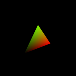
As an example, let's pass an OpenGL modelview and projection matrix as uniform variables to render a triangle with a rotating perspective camera. To this end, we extend the code from the initial example by two uniform variables. Once the change is applied in the shader code editor, two new input slots are created and matrix data nodes can be connected. The modelview matrix transforms the mesh from its local coordinate system into the camera coordinate system and the projection matrix performs the camera's perspective projection.
#version 300 es
in vec3 position; // input vertex position from mesh
in vec2 texcoord; // input vertex texture coordinate from mesh
in vec3 normal;   // input vertex normal from mesh

// uniform variables are exposed as node slots
uniform mat4 projection; //description="camera projection matrix"
uniform mat4 modelview; // description="modelview transformation"

out vec2 tc; // output texture coordinate of vertex
out vec4 fn; // output fragment normal of vertex

void main(){
  tc = texcoord;
  fn = vec4(normal, 1.0);
  gl_Position = projection * modelview * vec4(position, 1.0);
}
#version 300 es
precision highp float;
out vec4 outColor;
in vec2 tc; // texture coordinate of pixel (interpolated)
in vec4 fn; // fragment normal of pixel (interpolated)

void main() {
  outColor = vec4(tc.x, tc.y, 0.0, 1.0);
}
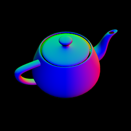
Transforming surface normals
When transforming surface normals, it should be considered that a normal is a unit vector that is neither translated nor scaled during a transformation with the modelview matrix. It should be only rotated. As shown in Chapter 9 of the lecture, the required transformation matrix is the transposed inverse of the modelview matrix.
This is demonstrated in the following example. Different outputs can be selected with the a uniform variable "mode":
#version 300 es
in vec3 position; // input vertex position from mesh
in vec2 texcoord; // input vertex texture coordinate from mesh
in vec3 normal;   // input vertex normal from mesh

// uniform variables are exposed as node slots
uniform int mode; // description="select mode" defaultval="1"
uniform mat4 projection; //description="camera projection matrix"
uniform mat4 modelview; // description="modelview transformation"

// transposed inverse modelview matrix
//(not exposed as slot but computed from "modelview")
uniform mat4 modelviewTransposedInverse;

out vec4 forFragColor; // output per-vertex color

void main(){
    gl_Position = projection * modelview * vec4(position,  1.0);
    vec4 n = modelviewTransposedInverse * vec4(normal, 0.0);
    vec3 nn = normalize(n.xyz);
    forFragColor = vec4(1.0, 0.0, 0.0, 1.0);
    if(mode == 1) forFragColor = vec4(nn, 1.0);
    if(mode == 2) forFragColor = vec4(normal, 1.0);
    if(mode == 3) forFragColor = gl_Position;
    if(mode == 4) forFragColor = vec4(position, 1.0);
    if(mode == 5) forFragColor = vec4(texcoord, 0.0, 1.0);
}
#version 300 es
precision highp float;
out vec4 outColor;
in vec4 forFragColor; // interpolated fragment color

void main() {
  outColor = forFragColor;
}
Textures
2D textures can be accessed by defining a uniform variable of the typesampler2D. Texture parameters can be selected using name-value pairs
in the comment after its definition.
This includes magnification and minification filters and wrap parameters. The following table enlists the supported options:
| Texture Parameter Name | Possible Values |
| mag_filter | NEAREST (default) LINEAR |
| min_filter | NEAREST LINEAR LINEAR_MIPMAP_NEAREST (default) LINEAR_MIPMAP_LINEAR |
| wrap_s | CLAMP_TO_EDGE (default) REPEAT MIRRORED_REPEAT |
| wrap_t | CLAMP_TO_EDGE (default) REPEAT MIRRORED_REPEAT |
Here is an example:
#version 300 es
in vec3 position; // input vertex position from mesh
in vec2 texcoord; // input vertex texture coordinate from mesh
in vec3 normal;   // input vertex normal from mesh

// uniform variables are exposed as node slots
uniform mat4 projection; //description="camera projection matrix"
uniform mat4 modelview; // description="modelview transformation"

// transposed inverse modelview transformation
// (not exposed as slot but computed from "modelview")
uniform mat4 modelviewTransposedInverse;

out vec2 tc; // output texture coordinate of vertex
out vec3 fn; // output fragment normal of vertex

void main(){
  tc = texcoord;
  fn = normalize( vec3( modelviewTransposedInverse * vec4(normal, 0.0) ) );
  gl_Position = projection * modelview * vec4(position, 1.0);
}
#version 300 es
precision highp float;
out vec4 outColor;
in vec2 tc; // texture coordinate of pixel (interpolated)
in vec3 fn; // fragment normal of pixel (interpolated)

uniform sampler2D myTexture; // wrap_s="REPEAT" wrap_t="REPEAT"
uniform float texScale;  // description="texture scaling" defaultval="2.0"
uniform int gsnMeshGroup; // not exposed as slot

void main() {
  vec3 normal = normalize(fn);
  vec4 texColor  = texture(myTexture, texScale * tc);
  vec4 col = vec4(0.0, 0.0, 0.0, 1.0);
  if(gsnMeshGroup == 0) col = vec4(1.0, 0.0, 0.0, 1.0);
  if(gsnMeshGroup == 1) col = vec4(0.0, 1.0, 0.0, 1.0);
  if(gsnMeshGroup == 2) col = vec4(0.0, 0.0, 1.0, 1.0);
  if(gsnMeshGroup == 3) col = vec4(1.0, 1.0, 0.0, 1.0);
  outColor = col * texColor;
}
Blinn-Phong BRDF with a Directional Light
The next few examples demonstrate how to perform shading of a 3D mesh using different BRDF models. An introduction to this topic can be found in Chapter 10.1 of the lecture on graphics programming.
In this first example, the shader computes the output pixel color according to the Blinn-Phong BRDF using a single directional light:
#version 300 es
precision highp float;
in vec3 position; // input vertex position from mesh
in vec2 texcoord; // input vertex texture coordinate from mesh
in vec3 normal;   // input vertex normal from mesh

uniform mat4 cameraLookAt; //camera look at matrix
uniform mat4 cameraProjection; //camera projection matrix
uniform mat4 meshTransform; // mesh transformation
uniform mat4 meshTransformTransposedInverse; // transposed inverse of meshTransform

out vec2 tc; // output texture coordinate of vertex
out vec3 wfn; // output fragment normal of vertex in world coordinate system
out vec3 vertPos; // output 3D position in world coordinate system

void main(){
  tc = texcoord;
  wfn = vec3(meshTransformTransposedInverse * vec4(normal, 0.0));
  vec4 vertPos4 = meshTransform * vec4(position, 1.0);
  vertPos = vec3(vertPos4) / vertPos4.w;
  gl_Position = cameraProjection * cameraLookAt * vertPos4;
}
#version 300 es
precision highp float;
out vec4 outColor;

in vec2 tc; // texture coordinate of pixel (interpolated)
in vec3 wfn; // fragment normal of pixel (interpolated)
in vec3 vertPos; // fragment vertex position (interpolated)

uniform vec4 ambientColor; // description="ambient color" defaultval="0.05, 0.0, 0.0, 1.0"
uniform vec4 diffuseColor; // description="diffuse color" defaultval="0.2, 0.0, 0.0, 1.0"
uniform vec4 specularColor; // description="specular color" defaultval="1.0, 1.0, 1.0, 1.0"
uniform float shininess; // description="specular shininess exponent" defaultval="20.0"
uniform vec4 lightColor; // description="color of light" defaultval="1.0, 1.0, 1.0, 1.0"
uniform vec3 lightDirection; // light direction in world space
uniform vec3 cameraPosition; // camera position in world space

const float irradiPerp = 1.0;

vec3 rgb2lin(vec3 rgb) { // sRGB to linear approximation
  return pow(rgb, vec3(2.2));
}

vec3 lin2rgb(vec3 lin) { // linear to sRGB approximation
  return pow(lin, vec3(1.0 / 2.2));
}

vec3 blinnPhongBRDF(vec3 lightDir, vec3 viewDir, vec3 normal,
            vec3 phongDiffuseCol, vec3 phongSpecularCol, float phongShininess) {
  vec3 color = phongDiffuseCol;
  vec3 halfDir = normalize(viewDir + lightDir);
  float specDot = max(dot(halfDir, normal), 0.0);
  color += pow(specDot, phongShininess) * phongSpecularCol;
  return color;
}

void main() {
  vec3 lightDir = normalize(-lightDirection); // towards light
  vec3 viewDir = normalize(cameraPosition - vertPos);
  vec3 n = normalize(wfn);

  vec3 radiance = rgb2lin(ambientColor.rgb);

  // irradiance contribution from light
  float irradiance = max(dot(lightDir, n), 0.0) * irradiPerp;
  if(irradiance > 0.0) { // if receives light
    vec3 brdf = blinnPhongBRDF(lightDir, viewDir, n, rgb2lin(diffuseColor.rgb),
                               rgb2lin(specularColor.rgb), shininess);
    radiance += brdf * irradiance * lightColor.rgb;
  }

  outColor.rgb = lin2rgb(radiance);
  outColor.a = 1.0;
}

Phong BRDF
You can also use other shading models, e.g., for Phong, the BRDF function becomes:
vec3 phongBRDF(vec3 lightDir, vec3 viewDir, vec3 normal,
           vec3 phongDiffuseCol, vec3 phongSpecularCol, float phongShininess) {
  vec3 color = phongDiffuseCol;
  vec3 reflectDir = reflect(-lightDir, normal);
  float specDot = max(dot(reflectDir, viewDir), 0.0);
  color += pow(specDot, phongShininess) * phongSpecularCol;
  return color;
}
Modified Phong BRDF
Or for modified Phong (with a normalized diffuse and specular component), the BRDF is:
#define RECIPROCAL_PI 0.3183098861837907
#define RECIPROCAL_2PI 0.15915494309189535

vec3 modifiedPhongBRDF(vec3 lightDir, vec3 viewDir, vec3 normal,
                       vec3 phongDiffuseCol, vec3 phongSpecularCol, float phongShininess) {
  vec3 color = phongDiffuseCol * RECIPROCAL_PI;
  vec3 reflectDir = reflect(-lightDir, normal);
  float specDot = max(dot(reflectDir, viewDir), 0.001);
  float normalization = (phongShininess + 2.0) * RECIPROCAL_2PI;
  color += pow(specDot, phongShininess) * normalization * phongSpecularCol;
  return color;
}
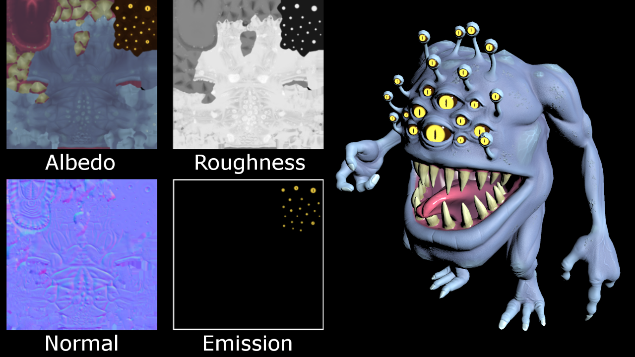
Here is another example for directional lighting in which shading parameters are read from textures and vary over the surface:
GGX Microfacet BRDF
The GGX microfacet BRDF [Walter et al. 2007, Disney 2012, Unreal 2013] is popular in physical-based rendering (PBR) and can be implemented with the following shader code:
vec3 fresnelSchlick(float cosTheta, vec3 F0) {
  return F0 + (1.0 - F0) * pow(1.0 - cosTheta, 5.0);
}

float D_GGX(float NoH, float roughness) {
  float alpha = roughness * roughness;
  float alpha2 = alpha * alpha;
  float NoH2 = NoH * NoH;
  float b = (NoH2 * (alpha2 - 1.0) + 1.0);
  return alpha2 / (PI * b * b);
}

float G1_GGX_Schlick(float NoV, float roughness) {
  //float r = roughness; // original
  float r = 0.5 + 0.5 * roughness; // Disney remapping
  float k = (r * r) / 2.0;
  float denom = NoV * (1.0 - k) + k;
  return max(NoV, 0.001) / denom;
}

float G_Smith(float NoV, float NoL, float roughness) {
  float g1_l = G1_GGX_Schlick(NoL, roughness);
  float g1_v = G1_GGX_Schlick(NoV, roughness);
  return g1_l * g1_v;
}

vec3 microfacetBRDF(in vec3 L, in vec3 V, in vec3 N,
              in vec3 baseColor, in float metallicness,
              in float fresnelReflect, in float roughness) {

  vec3 H = normalize(V + L); // half vector

  // all required dot products
  float NoV = clamp(dot(N, V), 0.0, 1.0);
  float NoL = clamp(dot(N, L), 0.0, 1.0);
  float NoH = clamp(dot(N, H), 0.0, 1.0);
  float VoH = clamp(dot(V, H), 0.0, 1.0);

  // F0 for dielectics in range [0.0, 0.16]
  // default FO is (0.16 * 0.5^2) = 0.04
  vec3 f0 = vec3(0.16 * (fresnelReflect * fresnelReflect));
  // in case of metals, baseColor contains F0
  f0 = mix(f0, baseColor, metallicness);

  // specular microfacet (cook-torrance) BRDF
  vec3 F = fresnelSchlick(VoH, f0);
  float D = D_GGX(NoH, roughness);
  float G = G_Smith(NoV, NoL, roughness);
  vec3 spec = (F * D * G) / (4.0 * max(NoV, 0.001) * max(NoL, 0.001));

  // diffuse
  vec3 rhoD = baseColor;
  rhoD *= vec3(1.0) - F; // if not specular, use as diffuse (optional)
  rhoD *= (1.0 - metallicness); // no diffuse for metals
  vec3 diff = rhoD * RECIPROCAL_PI;

  return diff + spec;
}
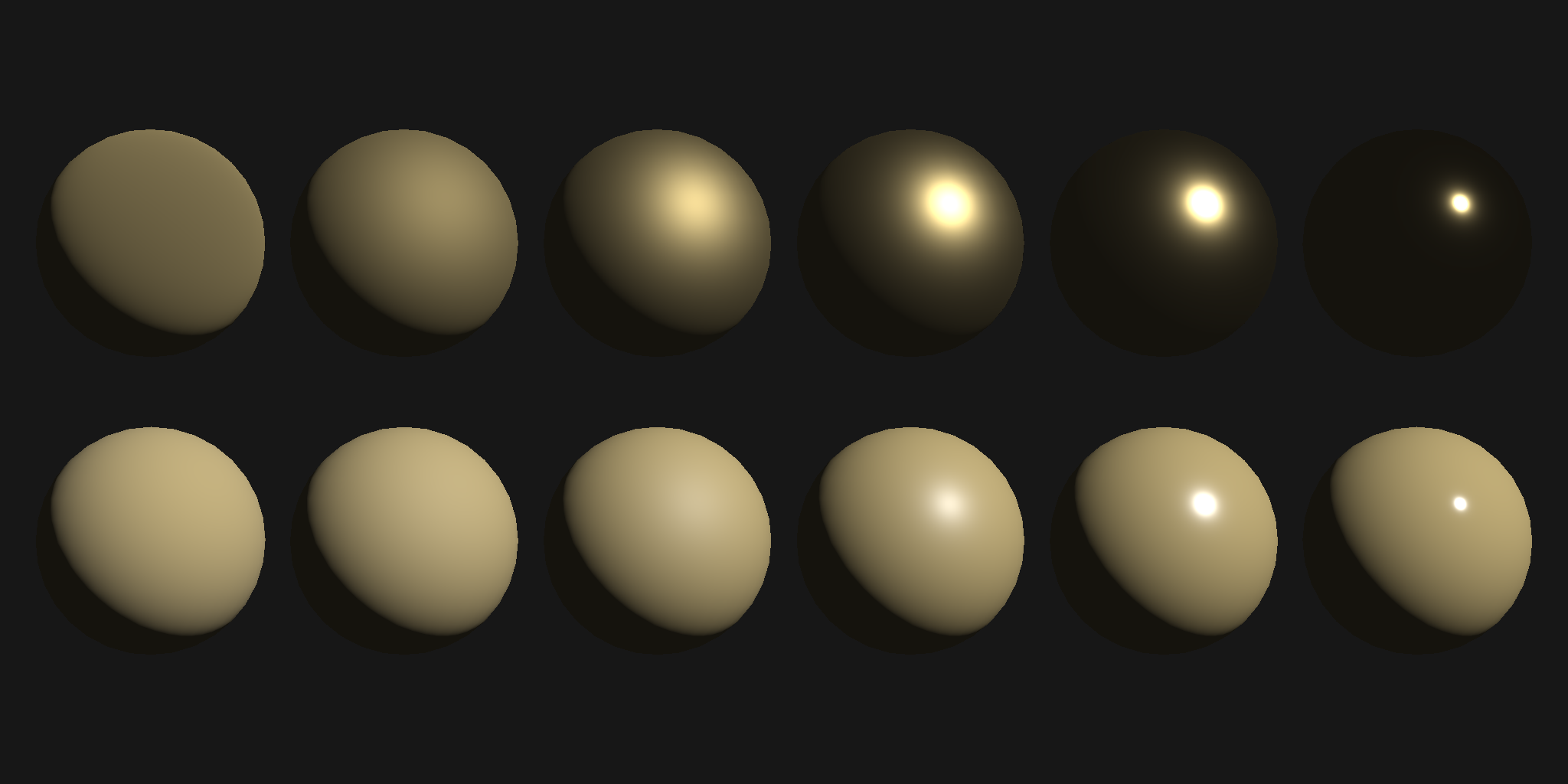
Image-based Lighting
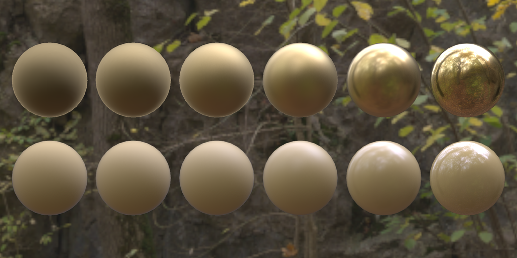
In this example, a spherical environment map is used to perform image-based lighting. An introduction to image-based lighting (IBL) can be found in Chapter 10.2 of the lecture on graphics programming.
Image-based lighting typically requires an environment map with high dynamic range. To this end, the GSN composer does support loading images in the Radiance HDR format.
The IBL examples follow the approach from Brian Karis, Epic Games (2013) and compute pre-filtered environment maps for the GGX microfacet BRDF by importance sampling. Using the "split sum approximation", real-time image-based lighting can be computed with to following GSL code:
#version 300 es
precision highp float;
in vec3 position; // input vertex position from mesh
in vec2 texcoord; // input vertex texture coordinate from mesh
in vec3 normal;   // input vertex normal from mesh

uniform mat4 cameraLookAt; //camera look at matrix
uniform mat4 cameraProjection; //camera projection matrix
uniform mat4 meshTransform0; // mesh0 transformation
uniform mat4 meshTransform1; // mesh1 transformation
uniform mat4 meshTransform0TransposedInverse; // transposed inverse of meshTransform0
uniform mat4 meshTransform1TransposedInverse; // transposed inverse of meshTransform1

uniform int gsnMeshGroup;

out vec2 tc; // output texture coordinate of vertex
out vec3 wfn; // output fragment normal of vertex in world coordinate system
out vec3 vertPos; // output 3D position in world coordinate system

void main(){
  mat4 meshTransform;
  mat4 meshTransformTransposedInverse;

  if(gsnMeshGroup == 0) {  // transformation of envmap sphere
   meshTransform = meshTransform0;
   meshTransformTransposedInverse = meshTransform0TransposedInverse;
  } else {  // transformation of 3D mesh
   meshTransform = meshTransform1;
   meshTransformTransposedInverse = meshTransform1TransposedInverse;
  }
  tc = texcoord;
  wfn = vec3(meshTransformTransposedInverse * vec4(normal, 0.0));
  vec4 vertPos4 = meshTransform * vec4(position, 1.0);
  vertPos = vec3(vertPos4) / vertPos4.w;
  gl_Position = cameraProjection * cameraLookAt * vertPos4;
}
#version 300 es
precision highp float;
precision highp int;
out vec4 outColor;

#define PI 3.1415926535897932384626433832795

in vec2 tc; // texture coordinate of pixel (interpolated)
in vec3 wfn; // fragment normal of pixel (interpolated)
in vec3 vertPos; // fragment vertex position (interpolated)
uniform sampler2D envMapImage; // min_filter="LINEAR_MIPMAP_NEAREST"
uniform sampler2D prefilteredEnvmap; // min_filter="LINEAR_MIPMAP_LINEAR"
uniform sampler2D brdfIntegrationMap;
uniform sampler2D diffuseMap; // min_filter="LINEAR" mag_filter="LINEAR"
uniform vec4 baseColor; // description="albedo for dielectrics or specular for metals"
uniform float roughness; // description="roughness in range [0.0, 1.0]"
uniform float metallic; // description="set to 0.0 for dielectrics and 1.0 for metals"
uniform float reflectance; // description="Fresnel reflectance for non-metallic materials"
uniform bool showBackground; // defaultval="true"
uniform vec3 cameraPos; // description="camera position in global coordinate system"
uniform int mipCount; // description="number of mipmap levels in the prefilteredEnvmap"
uniform int gsnMeshGroup;

vec2 directionToSphericalEnvmap(vec3 dir) {
  float s = 1.0 - mod(1.0 / (2.0*PI) * atan(dir.y, dir.x), 1.0);
  float t = 1.0 / (PI) * acos(-dir.z);
  return vec2(s, t);
}

// adapted from "Real Shading in Unreal Engine 4", Brian Karis, Epic Games
vec3 specularIBL(vec3 F0 , float roughness, vec3 N, vec3 V) {
  float NoV = clamp(dot(N, V), 0.0, 1.0);
  vec3 R = reflect(-V, N);
  vec2 uv = directionToSphericalEnvmap(R);
  vec3 prefilteredColor = textureLod(prefilteredEnvmap, uv, roughness*float(mipCount)).rgb;
  vec4 brdfIntegration = texture(brdfIntegrationMap, vec2(NoV, roughness));
  return prefilteredColor * ( F0 * brdfIntegration.x + brdfIntegration.y );
}

vec3 diffuseIBL(vec3 normal) {
  vec2 uv = directionToSphericalEnvmap(normal);
  return texture(diffuseMap, uv).rgb;
}

vec3 fresnelSchlick(float cosTheta, vec3 F0) {
  return F0 + (1.0 - F0) * pow(1.0 - cosTheta, 5.0);
}

void main() {
  vec3 normal = normalize(wfn);
  vec3 viewDir = normalize(cameraPos - vertPos);

  if(gsnMeshGroup == 0) {
    // render envmap
    if(showBackground) {
      // color of envmap sphere
      outColor.rgb = texture(envMapImage, vec2(1.0-tc.x, tc.y)).rgb;
      outColor.a = 1.0;
    } else {
      discard;
    }
  } else {
    // render 3D mesh with image-based lighting
    vec3 baseCol = pow(baseColor.rgb, vec3(2.2));

    // F0 for dielectics in range [0.0, 0.16]
    // default FO is (0.16 * 0.5^2) = 0.04
    vec3 f0 = vec3(0.16 * (reflectance * reflectance));
    // in case of metals, baseColor contains F0
    f0 = mix(f0, baseCol, metallic);

    // compute diffuse and specular factors
    vec3 F = fresnelSchlick(max(dot(normal, viewDir), 0.0), f0);
    vec3 kS = F;
    vec3 kD = 1.0 - kS;
    kD *= 1.0 - metallic;

    vec3 specular = specularIBL(f0, roughness, normal, viewDir);
    vec3 diffuse = diffuseIBL(normal);

    outColor.rgb = pow(kD * baseCol * diffuse + specular, vec3(1.0/2.2));
    outColor.a = 1.0;
  }
}

Multiple Render Targets / G-Buffer
WebGL2 supports rendering to multiple render targets (MRT) in a single render pass. This can be achieved by specifying
multiple out variables in the fragment shader. To this end, the GLSL layout qualifier
must be used with consecutive locations starting from 0. For each out variable the GSN Composer automatically
creates a corresponding output slot for the shader node.
The following example shows how to create a GLSL shader that renders positions, normals, and texture coordinates to multiple render targets as a prerequisite for deferred shading. The collection of a scene's projected geometry information is also referred to as a geometry buffer (G-buffer).
#version 300 es
precision highp float;
in vec3 position; // input vertex position from mesh
in vec2 texcoord; // input vertex texture coordinate from mesh
in vec3 normal;   // input vertex normal from mesh

uniform mat4 cameraLookAt; //camera look at matrix
uniform mat4 cameraProjection; //camera projection matrix
uniform mat4 meshTransform; // mesh transformation
uniform mat4 meshTransformTransposedInverse; // transposed inverse of meshTransform

out vec2 tc; // output texture coordinate of vertex
out vec3 wfn; // output fragment normal of vertex in world space
out vec3 vertPos; // output 3D position in world space

void main(){
  tc = texcoord;
  wfn = vec3(meshTransformTransposedInverse * vec4(normal, 0.0));
  vec4 vertPos4 = meshTransform * vec4(position, 1.0);
  vertPos = vec3(vertPos4) / vertPos4.w;
  gl_Position = cameraProjection * cameraLookAt * vertPos4;
}
#version 300 es
precision highp float;
layout(location = 0) out vec4 outPosition;
layout(location = 1) out vec4 outNormal;
layout(location = 2) out vec4 outTexCoord;

in vec2 tc; // texture coordinate of pixel (interpolated)
in vec3 wfn; // fragment normal of pixel in world space (interpolated)
in vec3 vertPos; // fragment vertex position in world space (interpolated)

void main() {
  vec3 n = normalize(wfn);
  outPosition = vec4(vertPos, 1.0);
  outNormal = vec4(n, 1.0);
  outTexCoord = vec4(tc, 0.0, 1.0);
}
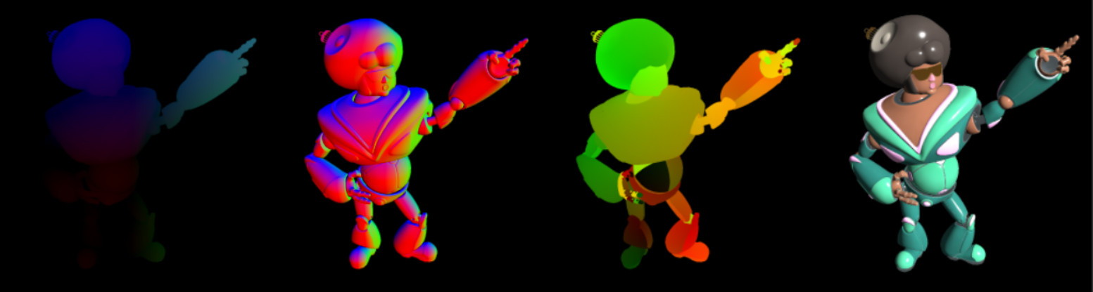
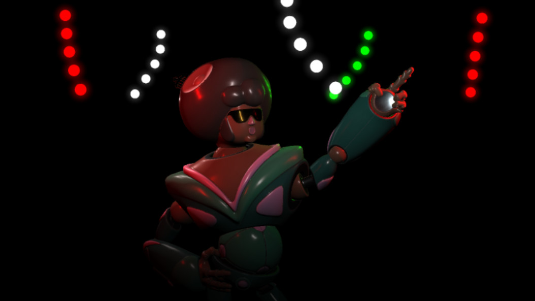
A G-buffer can be used for deferred shading. Deferred shading is especially useful for scenes with many dynamic lights, as demonstrated in the next example. For each light source, a quad is placed in screen-space and deferred shading is performed for each fragment of each "light quad" using the geometry information that is read from the G-buffer.
Advanced Options
Several advanced rendering options (such as disabling of the depth test, blending functions, or the backface-culling mode) can be changed by inserting an additional commented line somewhere in the shader code that starts with the keyword "gsnShaderOptions". The options can be selected using name-value pairs in the line after this keyword. The following table enlists the supported values:| Name | Possible Values |
| depth_test | ENABLE (default) DISABLE |
| cull_face | DISABLE (default) BACK FRONT FRONT_AND_BACK |
| blend_func | "srcFactor, dstFactor" where source and destination blending factors can be: ZERO, ONE, SRC_COLOR, ONE_MINUS_SRC_COLOR, DST_COLOR, ONE_MINUS_DST_COLOR, SRC_ALPHA, ONE_MINUS_SRC_ALPHA, DST_ALPHA, ONE_MINUS_DST_ALPHA Default is "ONE,ONE_MINUS_SRC_ALPHA" |
| blend_func_separate | "rgbSrcFactor, rbgDstFactor, aSrcFactor, aDstFactor"
such that RGB- and Alpha-channel source and destination blending factors can be chosen separately. Possible values are the same as for "blend_func". |
For example, the following line of shader code disables the depth test and uses (default) pre-multiplied alpha blending:
// gsnShaderOptions: depth_test="DISABLE" blend_func="ONE,ONE_MINUS_SRC_ALPHA"
Shaders Monthly
- What are Shaders? A Hands-on Introduction [Shaders Monthly #1]
- Perspective Projection in GLSL [Shaders Monthly #2]
- OpenGL Modelview Matrix and 3D Transformations [Shaders Monthly #3]
- Blinn Phong Shading: Theory and Implementation [Shaders Monthly #4]
- Texture Mapping in GLSL [Shaders Monthly #52]
- What are Mipmaps? Texture Filtering in GLSL [Shaders Monthly #6]
- Procedural Textures: A Practical Introduction [Shaders Monthly #7]
- Procedural Noise: Value and Gradient Noise in GLSL [Shaders Monthly #8]
- Microfacet BRDF: Theory and Implementation of Basic PBR Materials [Shaders Monthly #9]
- Importance Sampling: Image-based Lighting of a Lambertian Diffuse BRDF [Shaders Monthly #10]
- Image-based Lighting (IBL) of PBR Materials [Shaders Monthly #11]
- Halton Low-Discrepancy Sequence [Shaders Monthly #12]
- Sampling of Environment Maps for Image-based Lighting [Shaders Monthly #13]
- Deferred Shading [Shaders Monthly #14]
Please use the contact form or visit the forum on Reddit if you have questions or suggestions for improvement.