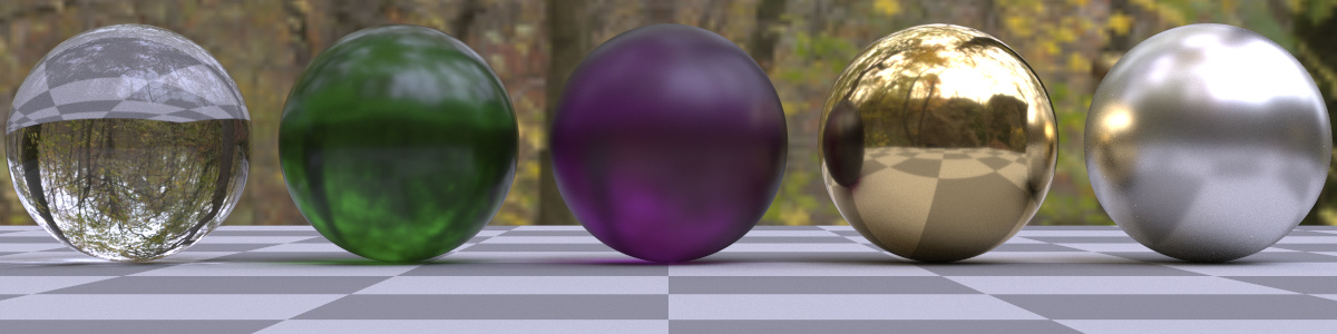
Custom Ray Tracing Shaders
The ImageShader plugin node of the GSN Composer executes user-provided GLSL fragment shader code and thereby enables the creation of a custom compute node for image generation.
Furthermore, there is a special pre-compiler that simulates the ray tracing shader pipeline from the Vulkan GL EXT ray tracing specification.
The pre-compiler translates the ray tracing shader code into a classic WebGL GLSL fragment shader.
A simple interface for custom raytracing shader development is the Vulkan GLSL Ray Tracing Emulator application. Please follow the provided tutorial to learn about the standardized ray tracing shader pipeline. Basic knowledge of the ray tracing shader pipeline is required to understand the following text.
To keep the interface as simple and accessible as possible, the online emulator application provides only a limited choice of pre-defined 3D meshes and textures. However, the shader code that is written in this emulator interface can be exported as a GSN Composer project. Once the project is exported, you can use custom 3D meshes and textures.
The following information is only required if you want to understand or change the structure of the exported GSN Composer project.
The pre-compiler is activated by adding the following line as the first line of the shader code:
// gsnShaderOptions: precompiler="GL_EXT_ray_tracing, recursion: 2"
The recursion option defines how often the traceRayEXT(...) function can be called
recursively.
When the GLSL code is exported from the online emulator application, the first line additionally contains the app option:
// gsnShaderOptions: precompiler="GL_EXT_ray_tracing, recursion: 2, app: 1"
The app option defines several additional uniform variables that are required inputs for
the simple interface of the emulator application. These are:
uniform int frameID;
uniform int frameSize;
uniform sampler2D g_PreviousImage;
uniform sampler2D texture0;
uniform sampler2D texture1;
uniform sampler2D texture2;
uniform sampler2D texture3;
uniform sampler2D texture4;
uniform float userParam0;
uniform float userParam1;
uniform float userParam2;
Furthermore, inputs for three BLASs (bottom-level acceleration structures) are generated. This is required because the emulator interface supports the selection of three BLASs. Each BLAS can be either a triangle mesh or a user-defined collection of axis-aligned bounding boxes (AABBs).
To change the number of BLASs, you can change the first line of the shader code to:
// gsnShaderOptions: precompiler="GL_EXT_ray_tracing, recursion: 2, app: 1, blas: 4"
Or if you do not require all the uniform variables from the emulator application:
// gsnShaderOptions: precompiler="GL_EXT_ray_tracing, recursion: 2, blas: 4"
If you want to use the function gsnGetPreviousPixel() in your code without the app option, you must activate
the previous option:
// gsnShaderOptions: precompiler="GL_EXT_ray_tracing, recursion: 2, blas: 4, previous: 1"In contrast to the
app option, the previous option only adds the following three uniform variables:
uniform int frameID;
uniform int frameSize;
uniform sampler2D g_PreviousImage;
3D.Compute.RaytracingShader.MeshToBLAS
The MeshToBLAS node converts a 3D mesh to a raytracing bottom-level acceleration structure (BLAS). In the GSN Composer, a BLAS input for the ImageShader node is represented as two images. Consequently, the MeshToBLAS node outputs two images. The first image contains the acceleration structure and can be connected to the ImageShader node via the input slot g_AccelStruct0. The second image contains the geometry data (vertex positions, vertex normals, texture coordinates, mesh group indices). It can be connected to the ImageShader node via the input slot g_Geometry0.
These input slots are generated by the ray tracing pre-compiler of the ImageShader node (see above). For the first BLAS, the pre-compiler provides the three input slots g_AccelStruct0, g_Geometry0, and g_ObjectToWorld0. The g_ObjectToWorld0 slot contains the BLAS's transformation matrix from object to world space. The digits at the end of each slot name correspond to the BLAS index. This means, for the second BLAS the inputs are g_AccelStruct1, g_Geometry1, and g_ObjectToWorld1.
3D.Compute.RaytracingShader.BoxesToBLAS
The BoxesToBLAS node converts a list of axis-aligned bounding boxes to a raytracing bottom-level acceleration structure (BLAS). Its output images can be used in the same way as the output images of the MeshToBLAS node (see above). The only difference is that the image for the geometry data now contains the bounding box information.
The axis-aligned bounding boxes can be defined by a text node at the elements input slot. The individual bounding boxes are separated in the text by a semicolon or a new line. After a semicolon, comments can be added after "//" (two slashes).
For example, the following text creates two bounding boxes:
(0.0, 1.0, 1.0), (0.5, 0.5, 0.5); // comment
(0.0, 0.0, 3.0), 0.5;
The first triplet of floating-point numbers defines the x-, y-, and z-coordinate of the center of the bounding box. The second triplet defines the bounding box's size in the x-, y-, and z-dimension.
If the size is the same for all three dimensions, a single floating-point number is sufficient.
3D.Compute.RaytracingShader.ToBLASMulti
The MeshToBLAS node or BoxesToBLAS node (see above) creates only a single raytracing bottom-level acceleration structure (BLAS). Therefore, each BLAS is encoded separately. This has the advantage that changes to the input trigger only the re-creation of a single BLAS.
A disadvantage of this approach is that each BLAS requires two input images that are connected to the g_AccelStruct and g_Geometry input slots of the ImageShader node. Consequently, access to the BLAS information in the shader requires two texture units per BLAS. WebGL2 typically allows only 16 texture units in total. This limits the total number of applicable BLASs.
The ToBLASMulti node converts multiple 3D meshes and axis-aligned bounding boxes to multiple BLASs, which are conjointly stored in a single output image.
The output image contains all the required data and can be connected to the ImageShader node via the input slot g_AccelStructMulti.
This input slot is generated by the ray tracing pre-compiler of the ImageShader node if the multi option is
enabled in the first line of the shader code:
// gsnShaderOptions: precompiler="GL_EXT_ray_tracing, recursion: 2, blas: 3, previous: 1, multi: 1"
The multi option can be also used in combination with the app option:
// gsnShaderOptions: precompiler="GL_EXT_ray_tracing, recursion: 2, app: 1, multi: 1"