2D Game Creation with the GSN Composer
The GSN Composer is a free web-based visual programming environment in which inputs and outputs of ready-made nodes are connected to generate an executable data-flow graph. The GSN Composer provides several image processing nodes that are intended to be used together to generate the basic components of a 2D game:- ImageProcessing.
Compute. Composite. Tiles - ImageProcessing.
Compute. Composite. Sprites - ImageProcessing.
Compute. Composite. SpriteGrid - ImageProcessing.
Compute. Composite. SpriteSheet
ImageProcessing.Compute.Composite.Tiles
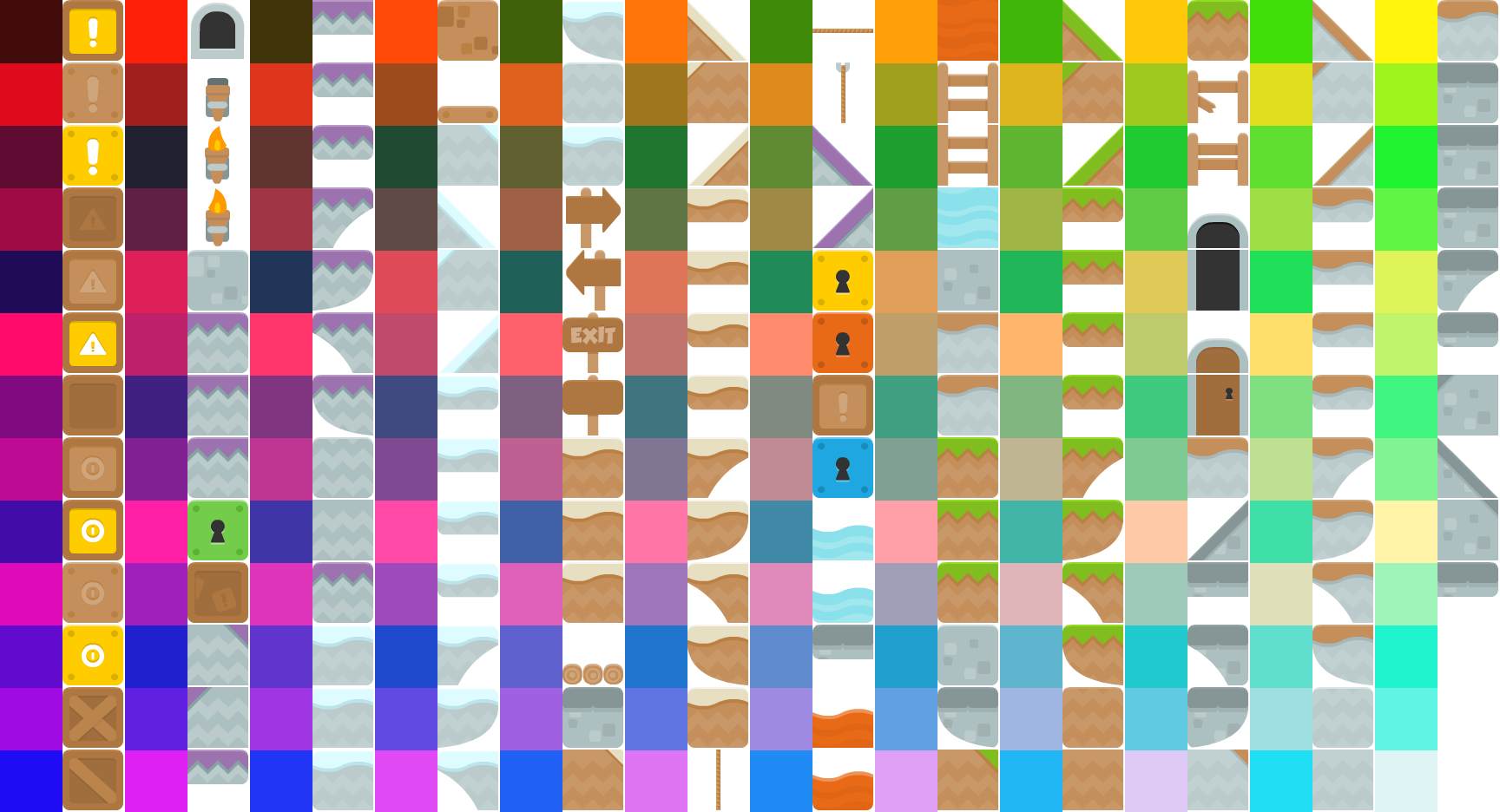
This node composites an output image from a tile map according to a layout image in which each pixel represents a tile. The image below shows a typical tile map (also called tile atlas).
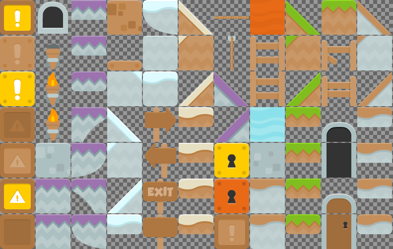
Tile maps are very useful for games in which the 2D world is build from rectangular 2D patches. The tile map is an image in which all required tiles are collected. To use a tile map within the Composite.Tiles node (described here), it is a requirement that all tiles within the tile map image must have the same size. If you have an element that does not fit into a tile, it is obviously possible to split it into multiple tiles, as it is done for the two doors in the tile map above. The input slots TileSizeX and TileSizeY allow specifiying the width and height of a tile within the tile map. The inputs TileGapX and TileGapY set the gap in x- and y-direction between the tiles, e.g. in the tile map above the gap is 2 pixels in both directions.
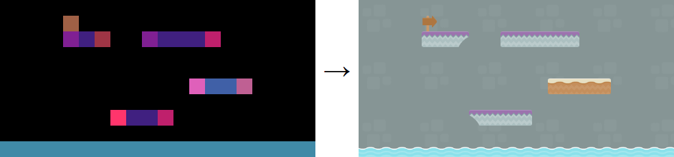
To build a 2D world, the tiles are instantiated by a layout image in which each pixel corresponds to an instantiated tile (as illustrated in the image above). Even a small layout image will result in a large output image, because for each input pixel a complete tile is placed. Let's assume the tile size is 100 x 100 pixels, then a 50 x 50 pixel layout image would already result in a 5000 x 5000 pixel output image.
Often not the complete 2D world should be visible but typically only a cut-out sections that follows the player. Therefore, the dimensions of the output image can be selected via the width and height input slots. The offsetX and offsetY input slots define the position of the cut-out section as an offset to the upper left corner of the complete 2D world. In fact, the complete 2D world is never create (also not internally) but only the currently required tiles are drawn into the output image.
The color of the pixel in the layout image defines, which tile from the tile map is selected. Each RGBA pixel stores a red, green, blue and alpha component in the range [0.0, 1.0]:
- The green component of the pixel color defines the x-location in the tile map: 0.0 is the leftmost, 1.0 is the rightmost tile, and in-between values are linearly interpolated.
- The blue component of the pixel color defines the y-location in the tile map: 0.0 is the topmost tile, 1.0 the bottommost tile, and in-between values are linearly interpolated.
- The red component can be arbitrarily selected such that employed pixel colors in the layout image are most distinguishable from one another. However, a red component below 0.1 will cause the tile to be left blank. This way, a black pixel in the layout images corresponds to empty space in the output image.
The example linked below generates a color map for each tile of an given tilemap, which can be very helpful as a reference to draw the layout image.
ImageProcessing.Compute.Composite.Sprites
This node composites an image from sprites that are collectively passed to the node as a sprite sheet image (also called sprite map or sprite atlas). Whereas the Composite.Tiles node (described above) is useful to generated static (non-changing) elements of a 2D world, the Composite.Sprites node (described here) is intended to control the dynamic game elements (e.g., a walking character, flying bullets, or attacking enemies).
Furthermore, in contrast to a tile map, in which the tiles are expected to be arranged in a fixed rectangular grid, the sprites in a sprite sheet can be freely positioned and can have arbitrary width and height.
As a consequence, in order to composite the sprite regions into the output image, the location of a sprite in the sprite sheet must be somehow defined. To this end, a text node can be connected to the SpriteInfo slot. In the text, each line describes the location of a sprite in the sprite sheet with the format:
[id]: [x] [y] [width] [height]
where [x] and [y] define the top-left corner of the sprite and are specified as the offset to the top-left corner of the sprite sheet image (in pixels). The identifier [id] must be an positive integer number. The identifiers must be unique but do not have to be consecutive.
Lastly, the positions of the sprites in the output image must be defined. Typically, the positions change with every frame and, consequently, a fast interface is required. Therefore, the positional information is encoded into a signal node connected to the positions input slot. In this signal, every four consecutive values specify the sprite identifier, x-position, y-position, and rotation [id, xPos, yPos, rot]. The x- and y- positions are given in pixels relative to the center of the output image and the rotation of the sprite is given in degrees.
It is also possible to flip the sprite horizontally by negating the sprite identifier. If this feature is required, the identifier 0 should be avoided because it can not be negated. A vertical flip can be achieved by a rotation about 180 degrees and a horizonal flip.
As it is demonstrated in the example below, several thousands of sprites can be handled at interactive speed (dependent on the capabilities of the available graphics card). Still the Composite.Tiles node (described above) executes even faster, which is why non-dynamic background should not be generated with the Composite.Sprites node (described here).
ImageProcessing.Compute.Composite.SpriteGrid
This node composites sprites into a regular grid in the output image. This is very useful for dynamically changing elements that are positioned at regular grid locations. A typically usage scenario would be to display the current score and other game information in a HUD (head-up display). To this end, the SpriteSheet and SpriteInfo slots can be used the same way as in the Composite.Sprites node (described above). However, a small difference is that the identifers [id] in the sprite information text
[id]: [x] [y] [width] [height]
should no longer be a positive numbers with multiple digits but can be any single alphanumeric character.
The grid spacing can by set via the TileSizeX and TileSizeY input slots.
Finally, sprites can then be instantiated by a text node connected to the LayoutText input slot. In this text, each letter corresponds to a sprite from the sprite map with the corresponding identifier (alphanumeric character). If the identifiers is not available in the sprite information text, the corresponding grid cell is left blank. By adding line breaks to the layout text, new grid rows can be created. A space character fills half a grid cell. Consequently, two spaces should be used to remain in the grid raster.
The example below demonstrates how to generate a scoreboard for a 2D game using the SpriteGrid node.
ImageProcessing.Compute.Composite.SpriteSheet
This node packs multiple images into a sprite sheet (also called sprite map or sprite atlas). The output is indented to be used with a Composite.Sprite node.
The example below demonstrates how to generate a sprite sheet from multiple input images.