3D.Compute.Render.MeshOrbit
This node renders a 3D mesh with an orbiting camera. It is intended for debugging the information contained in a mesh node (such as positions, per-vertex normals, and texture coordinates).

As shown in the figure above, the virtual camera is rotating around the 3D mesh on a circular orbiting path with a radius of $r=1.75\,d$, where $d$ is the largest dimension of the axis-aligned bounding box for the 3D mesh. The camera has a fixed vertical field of view angle of 60 degrees.
The orbit plane input slot selects the plane in which the orbit path lies ($x$-$y$, $x$-$z$, or $y$-$z$). In the figure above this is the $x$-$y$-plane.
The orbit offset input slot offsets the orbit path in a perpendicular direction to the selected orbit plane.
The type input slot selects which attribute of the mesh is shown color-coded as RGB:
- Type = 0: Position ($x$, $y$, $z$ coordinates of the vertices within the mesh's axis-aligned bounding box)
- Type = 1: Normal (per-vertex normal)
- Type = 2: TexCoord ($s$, $t$ texture coordinate)
- Type = 3: Group (mesh group index)
- Type = 4: Tangent (per-vertex tangent)
- Type = 5: Joints (per-vertex joint indices)
- Type = 6: JointWeights (per-vertex joint weights)
- Type = 7: VertexColor (per-vertex color)
- Type = 8: SelectWeight (per-vertex selection weight)
The wireframe input slot allows rendering the mesh in wireframe mode, which is useful for debugging the mesh's connectivity information.
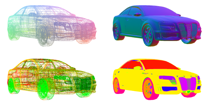
The image above shows color-coded positions (top left), color-coded normals (top right), color-coded texture coordinates (bottom left) and color coded mesh groups (bottom right). For postions and texture coordinates the wireframe mode was enabled.